Feature #5002
openEnsure current return paths via M.2 connector are sufficient
0%
Description
Hi,
5G NR, 4X4 MIMO, mmWave support, multiple-gigabit bandwidth processing etc. have increased the power requirements of data cards, over 3-4A at 3.3v. Return current paths through the M.2 connector should be inspected to ensure they are sufficient.
Files
Updated by mschramm over 3 years ago
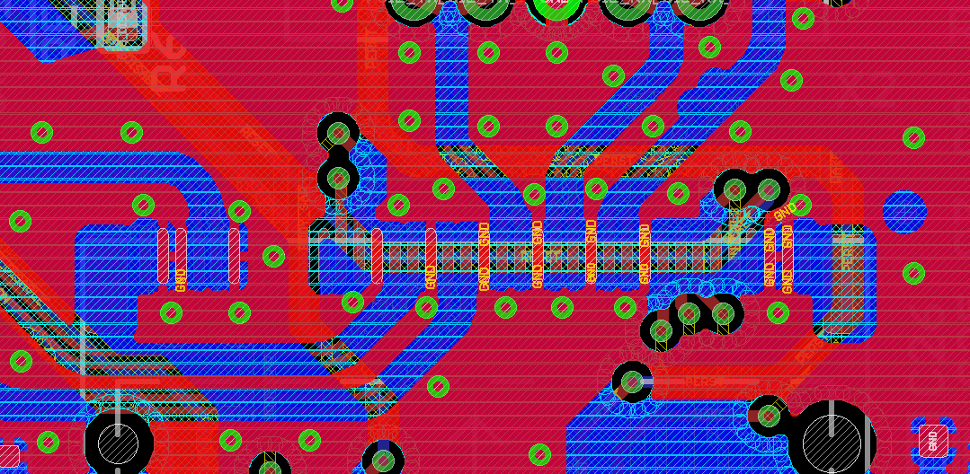
- File ngff-gnd-detail.png ngff-gnd-detail.png added
- Start date deleted (
02/01/2021)
marwalte wrote:
[...] have increased the power requirements of data cards, over 3-4A at 3.3v.
Please note that the LDO used is a 1,5A type (least guaranteed value of max. output current), this LDO detects a short when exposed to about 2,3A (can withstand forever and revover). Design aim here was rather to have an extra-fast transient response than a higher sustained current. If needed, we once might want to revise this (and could change it to a e.g. MIC2930x/2950x), but so far the LDO used did not disappoint.
Return current paths through the M.2 connector should be inspected to ensure they are sufficient.
While the M.2 socket has five pins for 3V3, it offers eleven GND pins. This is how they are connected to the three GND layer of this 4-layer PCBA - do you have any indication that this needs improvement?
Updated by marwalte over 3 years ago
Please note that the LDO used is a 1,5A type (least guaranteed value of max. output current), this LDO detects a short when exposed to about 2,3A (can withstand forever and recover)
Is that to say, this board has a guaranteed power limit of 4.95W, and will briefly operate up to 7.59W? This is a bit confusing, as USB 3.0 will provide 4.5w sustained, which is not much less than this board. I assumed (maybe incorrectly) that the external power supply would enable up to 15W power delivery to the modem (5V 3A).
Do you have any indication that this needs improvement?
I am not the right person to ask, unfortunately - this might require input from someone else. I think this feature request might have been better described as a confirmation of power delivery capability, and rating.
Updated by mschramm over 3 years ago
marwalte wrote:
Is that to say, this board has a guaranteed power limit of 4.95W, and will briefly operate up to 7.59W?
yes
This is a bit confusing, as USB 3.0 will provide 4.5w sustained, which is not much less than this board. I assumed (maybe incorrectly) that the external power supply would enable up to 15W power delivery to the modem (5V 3A).
We strongly suggest usage of an external power source. However, 0,9A via USB3 shall be possible here too. The power input selection jumper sources the LDO, so the constraints mentioned apply to either source (within max. LDO amperage). 5V/3A: modem always gets 3V3, not 5V, so that would be 10W @3A.
Do you have any indication that this needs improvement?
I am not the right person to ask, unfortunately - this might require input from someone else. I think this feature request might have been better described as a confirmation of power delivery capability, and rating.
OK, - I thought there already would have been flaws revealed.
Updated by marwalte over 3 years ago
5V/3A: modem always gets 3V3, not 5V, so that would be 10W @3A.
Apologies, I see how my other statement:
the external power supply would enable up to 15W power delivery to the modem (5V 3A).
Was ambiguous. I meant that the power supply that comes with the Osmocom board from Sysmocom can supply 5A, 3A - I assumed (incorrectly) that this would mean 3.3V ~4.5A was supplied to the card.
I can verify that there are cards that will consume for Sub-6 up to 3.3V 2.3A sustained under certain conditions, and mmWave will increase that as well (although there will be a split between the modem and the active mmWave antennas, that get extra power that is not directly from the card).
Updated by laforge over 3 years ago
If one wanted to properly test this, I think one would first need to generate some kind of "adapter PCB" that fits into the m2 socket (instead of a modem) and then use an electronic load ad different levels while taking thermal imaging of the PCB to see if the connector and/or the PCB land pattern reaches dangerous temperatures.
Now of course, what is "dangerous" can be argued...
In any case, the above involves a signficant investment of time (desinging that adapter, doing the prototype run, doing the test series) and I think it's unlikely that sysmocom wanted to currently invest effort into that unless there was a very specific demand/requirement from [volume] customers.
However, as this is a collaborative open source hardware project, we are of course very happy to receive contributions from anyone who wants to submit a layout/design for optimized thermal performance in high-current use cases.

