E1-to-RJ45 » History » Revision 12
« Previous |
Revision 12/14
(diff)
| Next »
laforge, 02/21/2016 11:04 AM
Howto build your E1<>RJ45 cable
We used a Cat-7 Ethernet cable to build our E1<>RJ45 cable to connect the BTS with the BSC.
Things you need:- one Cat-7 Ethernet cable
- two twinax plugs (BR2)
- some heat shrink tube
- soldering-iron
- multimeter (optional)
- a sharp knife :)
Step-by-step guide
One:
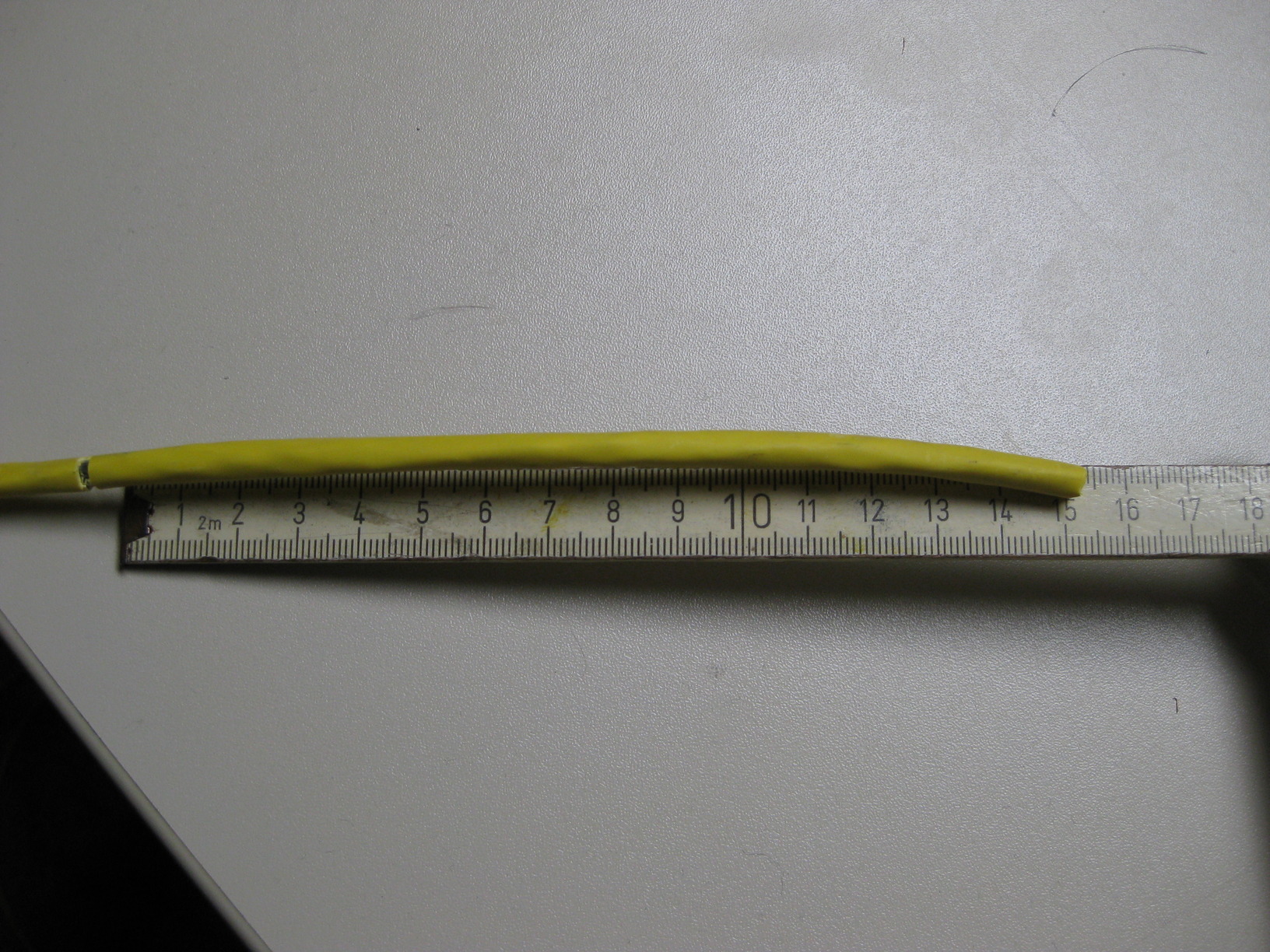
Take your cable and cut off one of the RJ45 connectors. Now use a ruler and make a slice so you can strip around 15 cm from your cable.

Two:
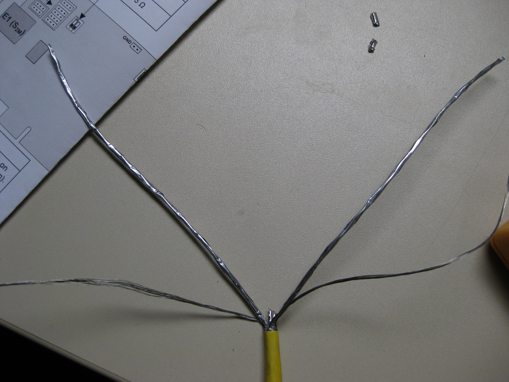
Split the wires from your cable. We need pin 1 and 2 for RX and pin 4 and 5 for TX, Use a Multimeter to determine the correct pairs. Cut off the other wires we do not need them (yet).


Three:
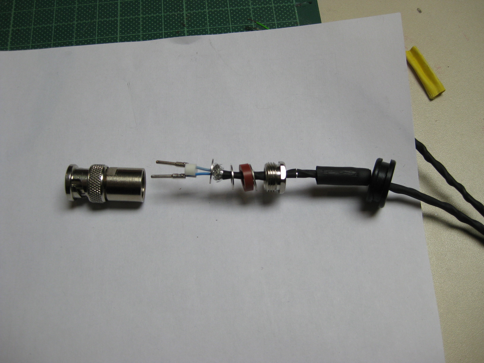
Sort your twinax plugs to make sure you build them in the right order. ;)
We used heat shrink tube to stabilize our cable around the plugs.
Image(IMG_0960-9.JPG, 15%) Image(IMG_0960-11.JPG, 15%)
Image(IMG_0960-12.JPG, 15%) Image(IMG_0960-17.JPG, 15%)
Four:
Now you can put everything on the first part of the cable and assemble it. Use a soldering-iron to fixate each of the two pins of the plug with your wires. You do not have to worry about the polarity inside the twinax plug.
Five:
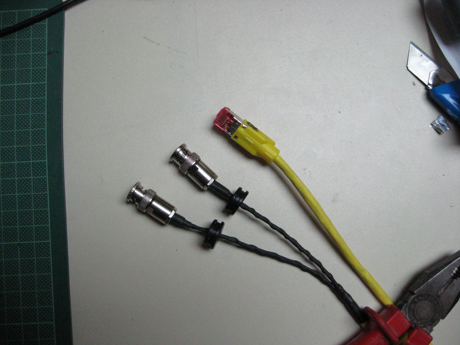
Repeat step three and four to build the second plug.
Done.
Detailed pinout
A detailed pinout for your reference:
Signals on the RJ45 plug:
             ++++++++++
            / /               / /|
           / /               / / |
          / /+++++++_/ /  |
         / ++++++++  /   |
        / / / / / / / / / / /    |
       / / / / / / / / / / /    /
      / /_/_/_/_/_/_/_/_/ /    /
      | | | | | | | | | | |   /
      | |8|7|6|5|4|3|2|1| |  /
      | |_|_|_|_|_|_|_|_| | /
      |+++++++++_|/
            |      |/
            \+++/

    1 = RX1
    2 = RX2
    3 = NC
    4 = TX1
    5 = TX2
    6 = NC
    7 = NC
    8 = NC

Signals on the twinax plugs:

     E1 Transmitter:
           +_
       .-_   '@-.
     .'           @.
    /     1      2  \
   :    ##     ##    ;
   |    ##     ##    |
   :                 ;
    \ ############# /
     @. ######### .'
       @-.++_.-'

    1 = TX1
    2 = TX2

     E1 Receiver:
           +_
       .-_   '@-.
     .'           @.
    /     1      2  \
   :    ##     ##    ;
   |    ##     ##    |
   :                 ;
    \ ############# /
     @. ######### .'
       @-.++_.-'

    1 = RX1
    2 = RX2

      Note: The drawings are showing the plugs point of view.
      Note: This is a differential connection with symetric signals
            so you do not have to care about the polarity.

Cable connection on the BS11:

  ---~++++_---
 /        12            \
 \        oo   oo       /
  ---~|+++_|---

    1 = RX (connect E1 Transmitter to that port)
    2 = TX (connect E1 Receiver to that port)
Updated by laforge about 8 years ago · 12 revisions

