Support #6464
openPut together Nokia TCSM2 system in Themyscira lab
60%
Description
There is one component of the traditional E1-based GSM architecture that has not been sufficiently explored in Osmocom yet: the TRAU. Getting a real historical TRAU, particularly one that implements GSM 08.62 TFO, up and running in a developer's lab would allow experiments and unlock knowledge that cannot be obtained in any other way:
- If we wish to implement the in-band TFO protocol in FOSS (in-band inside a G.711 PCM sample stream, which can be an RTP stream on "modern" IP-PSTN), the only way to assure correctness would be to test for interoperability against an existing implementation - yet the only existing implementations appear to be in TRAUs.
- TS 28.062 section C.3.2.1.1 defines some quite ambitious (and onerous to implement) rules for how one "shall" construct a "perfect" stream of TCH downlink frames (for call leg B DL) from a call leg A UL frame stream that can have gaps, errors, BFIs, misplaced SIDs and so forth. Knowledge of how a real historical vendor actually implemented these rules would be invaluable, and can be useful for OsmoMGW E1 interface mode: see #6463.
There is one historical TRAU that I am close to acquiring: Nokia TCSM2. Here are the bits of documentation I was able to find:
https://www.freecalypso.org/pub/GSM/Nokia_TCSM/
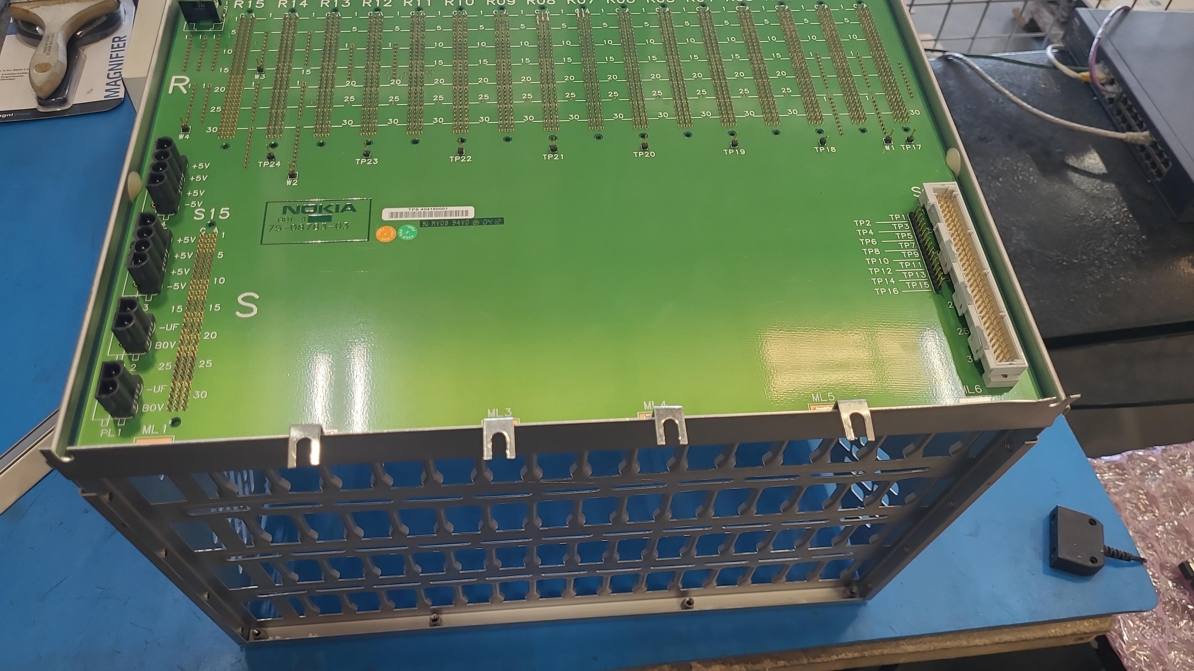
The parts I have on order from shields-e include one TC1C chassis, one power supply module for this chassis (goes from -48V to +5V and -5V), one TRCO card (main controller) and two TR16-S cards. (The ET subsystem, connected to TC1C with a ribbon cable, is to be acquired in a subsequent step.) As part of haggling with shields-e over the chassis which they initially declared as defective (a tiny cosmetic defect IMO), I got some pictures of this chassis:
https://www.freecalypso.org/members/falcon/pictures/Nokia_TCSM2/TC1C_chassis/
When this equipment arrives, my first order of business will be to power it up. I already have a "rectifier" that goes from regular AC mains to -48 VDC, but I need help identifying the power input connector on the Nokia box. This unknown connector is visible in this photo:
https://www.freecalypso.org/members/falcon/pictures/Nokia_TCSM2/TC1C_chassis/a03.jpeg
The box supports redundant power supplies, hence there are two connectors, but I reason that I should be able to connect just one -48V supply and get the box going. Does anyone recognize that two-pin power input connector on the back of Nokia's chassis? Any recommendations for a mating plug so I can assemble the cable for feeding power to this box?

