Support #6464
openPut together Nokia TCSM2 system in Themyscira lab
60%
Description
There is one component of the traditional E1-based GSM architecture that has not been sufficiently explored in Osmocom yet: the TRAU. Getting a real historical TRAU, particularly one that implements GSM 08.62 TFO, up and running in a developer's lab would allow experiments and unlock knowledge that cannot be obtained in any other way:
- If we wish to implement the in-band TFO protocol in FOSS (in-band inside a G.711 PCM sample stream, which can be an RTP stream on "modern" IP-PSTN), the only way to assure correctness would be to test for interoperability against an existing implementation - yet the only existing implementations appear to be in TRAUs.
- TS 28.062 section C.3.2.1.1 defines some quite ambitious (and onerous to implement) rules for how one "shall" construct a "perfect" stream of TCH downlink frames (for call leg B DL) from a call leg A UL frame stream that can have gaps, errors, BFIs, misplaced SIDs and so forth. Knowledge of how a real historical vendor actually implemented these rules would be invaluable, and can be useful for OsmoMGW E1 interface mode: see #6463.
There is one historical TRAU that I am close to acquiring: Nokia TCSM2. Here are the bits of documentation I was able to find:
https://www.freecalypso.org/pub/GSM/Nokia_TCSM/
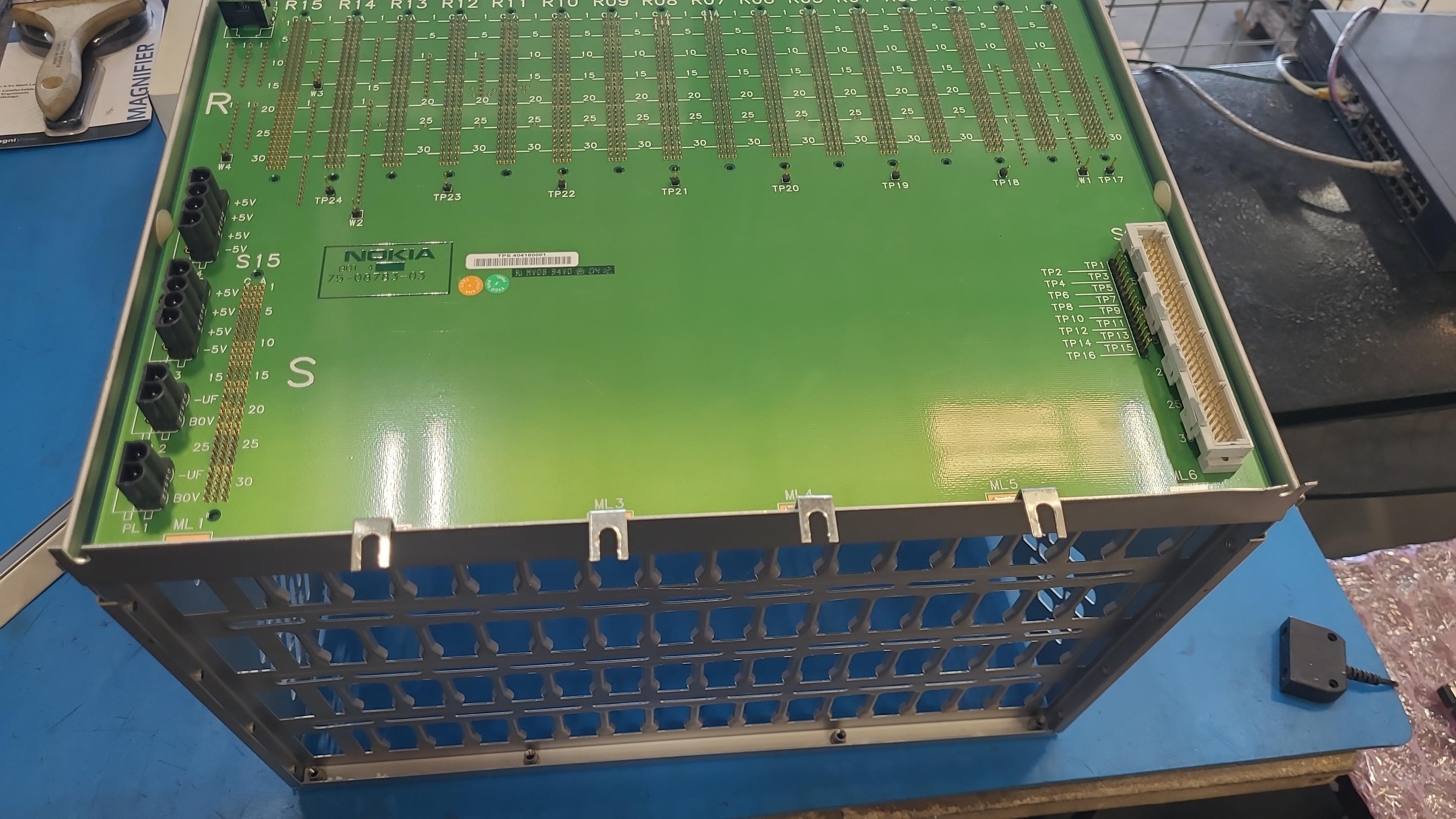
The parts I have on order from shields-e include one TC1C chassis, one power supply module for this chassis (goes from -48V to +5V and -5V), one TRCO card (main controller) and two TR16-S cards. (The ET subsystem, connected to TC1C with a ribbon cable, is to be acquired in a subsequent step.) As part of haggling with shields-e over the chassis which they initially declared as defective (a tiny cosmetic defect IMO), I got some pictures of this chassis:
https://www.freecalypso.org/members/falcon/pictures/Nokia_TCSM2/TC1C_chassis/
When this equipment arrives, my first order of business will be to power it up. I already have a "rectifier" that goes from regular AC mains to -48 VDC, but I need help identifying the power input connector on the Nokia box. This unknown connector is visible in this photo:
https://www.freecalypso.org/members/falcon/pictures/Nokia_TCSM2/TC1C_chassis/a03.jpeg
The box supports redundant power supplies, hence there are two connectors, but I reason that I should be able to connect just one -48V supply and get the box going. Does anyone recognize that two-pin power input connector on the back of Nokia's chassis? Any recommendations for a mating plug so I can assemble the cable for feeding power to this box?
Updated by falconia about 2 months ago
- Status changed from New to In Progress
- % Done changed from 0 to 10
The first shipment from shields-e arrived today: I got 1x TRCO board, 2x TR16-S boards and 1x power supply module. However, the chassis with the backplane is still missing: shields-e initially declared it as defective and dropped it from the order; I then told them that I am buying it as-is and they replied with agreement (even took payment on that "defective" chassis at a discounted price), but it didn't make the initial shipment. Now I need to nudge them some more to get this chassis shipped out, then wait for the 2nd shipment to arrive...
Preliminary notes from examination of TR16-S and TRCO boards are here:
Updated by falconia about 1 month ago
- % Done changed from 10 to 50
Today I got my partially complete TCSM2 system (TRCO and 2x TR16, but no Exchange Terminal modules) powered up for the first time. Despite the lack of ET2E or ET2A module, the system booted successfully and the local terminal interface (RS-232 port on TRCO card) is alive. Using this terminal interface, I was able to confirm the following key details:
- The software loaded on TRCO is good and complete;
- There are 3 DSP firmware versions installed, supporting circuit types A, B and F;
- TFO feature is available: if I set the circuit type to A (classic 16 kbit/s channels), I can then enable TFO for FR and EFR.
The next step is for me to buy (from the same source as the parts I already got) an ET2E module and ET1TC chassis to hold it, and then interconnect the two backplanes.
Updated by laforge about 1 month ago
- Project changed from Retronetworking to Retro-GSM
Updated by falconia 3 days ago
- % Done changed from 50 to 60
The ET2E module and the ET1TC chassis that holds it have arrived from shields-e. The next step is to construct the custom cable that interconnects TC1C and ET1TC backplanes, using the pinout tables included in the manual. The parts for making this cable (principally DIN 41612 connectors) are on order from Digi-Key.

