Bug #4782
closedngff-breakount doesn't work for RM500Q
Added by laforge over 3 years ago. Updated about 3 years ago.
100%
Description
It seems that (at least) Quectels first 5G modem in ngff form-factor (RM500Q) is a longer card type than what we designed the ngff-breakout for. Its width is 30mm, the length excluding connector is 48mm, (including connector: 52mm).
I would expect that more 5G modems, at least in the "early 5G days" actually will need this larger form-factor. This should be confirmed looking at [preliminary] data sheets.
I suppose we need to do a board spin with a larger PCB. That larger version then needs slightly more space between the NGFF slot and the 2.54mm pin connector, and a second SMT spacer for mounting the screw there.
While at it, we might also consier adding a 4th SMA connector, as the RM500Q now has four antenna connectors (MHF4)
Files
20201007_101506.jpg | View 20201007_101506.jpg | 175 KB | laforge, 10/07/2020 08:16 AM | ||
20201007_101521.jpg | View 20201007_101521.jpg | 1.17 MB | laforge, 10/07/2020 08:16 AM | ||
ngff-breakout_v3-obl.png | View ngff-breakout_v3-obl.png | 84.9 KB | mschramm, 10/26/2020 06:16 PM | ||
ngff-breakout_v3-3042-52.png | View ngff-breakout_v3-3042-52.png | 463 KB | mschramm, 10/26/2020 06:16 PM | ||
smt-post-2screw.jpg | View smt-post-2screw.jpg | 43.5 KB | mschramm, 10/26/2020 10:56 PM | ||
ngff-bo_v2-bottscrew.jpg | View ngff-bo_v2-bottscrew.jpg | 37.8 KB | mschramm, 10/28/2020 03:19 PM | ||
ngff-bo_v2-topscrew.jpg | View ngff-bo_v2-topscrew.jpg | 98.7 KB | mschramm, 10/28/2020 03:19 PM | ||
ngff-bo_v3-placement.png | View ngff-bo_v3-placement.png | 112 KB | mschramm, 11/09/2020 03:09 PM | ||
ngff-clip-anchor.jpg | View ngff-clip-anchor.jpg | 73.8 KB | mschramm, 11/09/2020 04:18 PM | ||
udoo-mounting-kit-pk.png | View udoo-mounting-kit-pk.png | 51.2 KB | mschramm, 11/09/2020 05:05 PM | ||
i-o-threads-spacer.jpg | View i-o-threads-spacer.jpg | 59.7 KB | mschramm, 11/09/2020 05:05 PM |
Updated by mschramm over 3 years ago
We designed this PCBA with M.2 3042 form factor modem cards in mind. The RM500Q is a 3052 M.2 card. I'd be easy to make that spin, but while Quectel, Simcom and SierraWireless 5G modem are 3052 M.2 cards, Telit offers a 5G M.2 modem (FN980m), advertised as being a 3050 card...
So for these 2mm difference surely a third SMT screw post wouldn't be possible. I just imagined an oblong hole / slot instead on n seperate posts, maybe we could hold a single of them movable it w/ a second screw+washer from bottom side.
Updated by laforge over 3 years ago
Let's go for the 3052 case. If Telit wants to do their own thing... so be it. I guess
they will have a hard time convincing mainboard manufacturers etc. to accomodate their special
form factor.
Updated by mschramm over 3 years ago
re Telit: they seem to be serious with their 3050 ff, OK, their problem.
More important:
- it appears, that we need to support more than one length option. Then the SMT posts should not get soldered, but fixed in either of two or three positions w/ a mandatory screw(+washer?) from bott side. Likely the screw's flat pan head will do without an additional washer.
- when touching this project, I'd like to exchange the pinheader area with the RF SMA-MHF4 area. This would also ease the space for a fourth SMA.
Updated by ben.foxmoore over 3 years ago
We (at Accelleran) have been developing our 5G SA software, and have noticed similar issues with the Sierra Wireless EM9190 and the M.2 - USB adapters available on the market today. It seems that your design has the same problem. Is there a plan to re-spin this design allowing for the 3052 format cards?
I'm aware that Sysmocom and Osmocom are not the same, but I know that batches of this design are sold by Sysmocom. If there's a question of MOQ, then we may be interested in committing to an order of a small number if that helps at all.
Updated by mschramm over 3 years ago
ben.foxmoore wrote:
It seems that your design has the same problem.
It is not a problem itself, it just results from several design decisions by the modem manufacturer and by sysmocom when first selecting interesting modem cards for such a break-out. At that time, no 5G cards were available, and the desired 4G cards are/have been 3042.
Is there a plan to re-spin this design allowing for the 3052 format cards?
Yes, right now I prepare a spin of that design for supporting 3042 and 3052 cards. If we decide to use an oblong hole for the SMT stand-off, this will support also 3050 modem cards; however, 3042 and 3052 are mandatory.
I'm aware that Sysmocom and Osmocom are not the same, but I know that batches of this design are sold by Sysmocom. If there's a question of MOQ, then we may be interested in committing to an order of a small number if that helps at all.
Appreciated, I know laforge listens.
Updated by mschramm over 3 years ago
- File ngff-breakout_v3-obl.png ngff-breakout_v3-obl.png added
- File ngff-breakout_v3-3042-52.png ngff-breakout_v3-3042-52.png added
- Status changed from New to In Progress
Just created two deviations from the NGFF/M.2 library element, one with another hole for 3052, the other with an oblong hole / slot covering the distance from xx42 to xx52 (see attached renderings). The PCBA has to become 1 cm 'taller' giving more room for four SMA. Looking at it, I see no urge to exchange SMA section with 28pin header, but we of course can do so.
Plated or unplated holes or slot for spacer: for a v3, I'd tend to unplated.
So for a future production run of a possible v3, everything so far is prepared in terms of main effort to support (at least) one more length option.
Updated by laforge over 3 years ago
On Mon, Oct 26, 2020 at 06:28:01PM +0000, mschramm [REDMINE] wrote:
Just created two deviations from the NGFF/M.2 library element, one with another hole for 3052, the other with an oblong hole / slot covering the distance from xx42 to xx52 (see attached renderings).
Thanks, I'd go for the 'two hole' solution, rather than the oblong hole.
The PCBA has to become 1 cm 'taller' giving more room for four SMA. Looking at it, I see no urge to exchange SMA section with 28pin header, but we of course can do so.
No need to create more work.
Plated or unplated holes or slot for spacer: for a v3, I'd tend to unplated.
How is the spacer mounted? With a screw from the bottom side?
Updated by mschramm over 3 years ago
- File smt-post-2screw.jpg smt-post-2screw.jpg added
laforge wrote:
Thanks, I'd go for the 'two hole' solution, rather than the oblong hole.
OK, dropping the other.
No need to create more work.
ACK.
Plated or unplated holes or slot for spacer: for a v3, I'd tend to unplated.
How is the spacer mounted? With a screw from the bottom side?
Yes, one of two variants to fix the spacer there. The mounting situation is the following one (see drawing). The spacer's body is 1.45mm high, has two steps: 0.65 top and 0,7mm bottom. Up is the mPCIe PCBA (0.8mm), the main PCBA is lowest (1.55mm) - we end up with 3.8...3.9mm, plated and tinned 4mm. This might work with 2x M2x2, but M2x3 are more common , so ordinary washers or shim rings, each wasting 1mm height, are needed then.
Besides this, one long screw with a nut (plus washer) would work too.
'Plated or unplated' here is secondary, as long as we don't solder the spacer anyway.
Updated by ben.foxmoore over 3 years ago
mschramm wrote:
ben.foxmoore wrote:
It seems that your design has the same problem.
It is not a problem itself, it just results from several design decisions by the modem manufacturer and by sysmocom when first selecting interesting modem cards for such a break-out. At that time, no 5G cards were available, and the desired 4G cards are/have been 3042.
Understood - I didn't mean to suggest it was a bug in the design or anything like that. We were also surprised to see that the 5G modems are using a different form factor.
Is there a plan to re-spin this design allowing for the 3052 format cards?
Yes, right now I prepare a spin of that design for supporting 3042 and 3052 cards. If we decide to use an oblong hole for the SMT stand-off, this will support also 3050 modem cards; however, 3042 and 3052 are mandatory.
OK, great - either design would work fine for us.
Updated by mschramm over 3 years ago
- File ngff-bo_v2-bottscrew.jpg ngff-bo_v2-bottscrew.jpg added
- File ngff-bo_v2-topscrew.jpg ngff-bo_v2-topscrew.jpg added
Quick check whether 2x M2 of 2 mm legth would do, and as expected they fit and hold the modem. In the picture of course the stand-off was soldered as I right now have no unsoldered one, but solder between metal stand-off and main PCB is usually not more than 0,05mm.
Instead of providing one M2 screw of 3mm, two M2 screws of 2mm and an unsoldered stand-off would provide mounting on either of both positions. The screws fit a PH1 screwdriver, so more than enough torque to ruin all threads involved. For increased requirements on holding force we will suggest usage of e.g. Loctite 222.
BTW, the PCIe_M.2 spec demands the stand-off being part of the system's GND path (as it has already been realized in v2), so we stay with a plated hole.
Updated by laforge over 3 years ago
mschramm wrote:
Instead of providing one M2 screw of 3mm, two M2 screws of 2mm and an unsoldered stand-off would provide mounting on either of both positions. The screws fit a PH1 screwdriver, so more than enough torque to ruin all threads involved. For increased requirements on holding force we will suggest usage of e.g. Loctite 222.
I'm not familiar with any sources for M2x2 screws with flat / large diameter head. The source we buy from has M2x3 as shortest length.
Can you locate such a source?
Updated by mschramm over 3 years ago
laforge wrote:
Can you locate such a source?
We have a small lab stock of them, two years old, no obvious manufacturer/distri on it. Sent you a pm with a photo of its label.
Updated by mschramm over 3 years ago
- File ngff-bo_v3-placement.png ngff-bo_v3-placement.png added
- File ngff-clip-anchor.jpg ngff-clip-anchor.jpg added
- File udoo-mounting-kit-pk.png udoo-mounting-kit-pk.png added
- File i-o-threads-spacer.jpg i-o-threads-spacer.jpg added
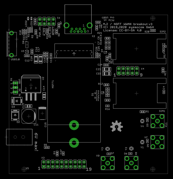
committed a v3 candidate for 3042 and 3052 cards. For the details on the mounting holes, this is preliminary as long as we're not done with the changed mounting situation.
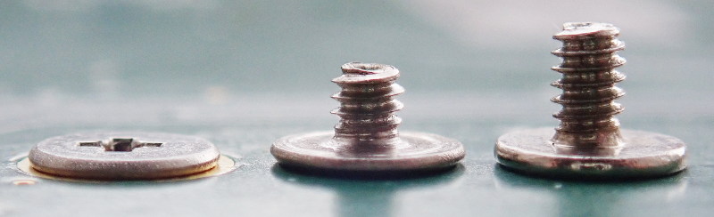
I've again spent too much time in finally not finding any decent source for M2 screws w/ wafer head (or broad-head) in 2 mm length beside more or less random eb*y stores in CN. The very few exceptions selling 'laptop screws' believe that they trade gold, and hence their ridiculous prices.
During search, some more M.2 mounting options came across:
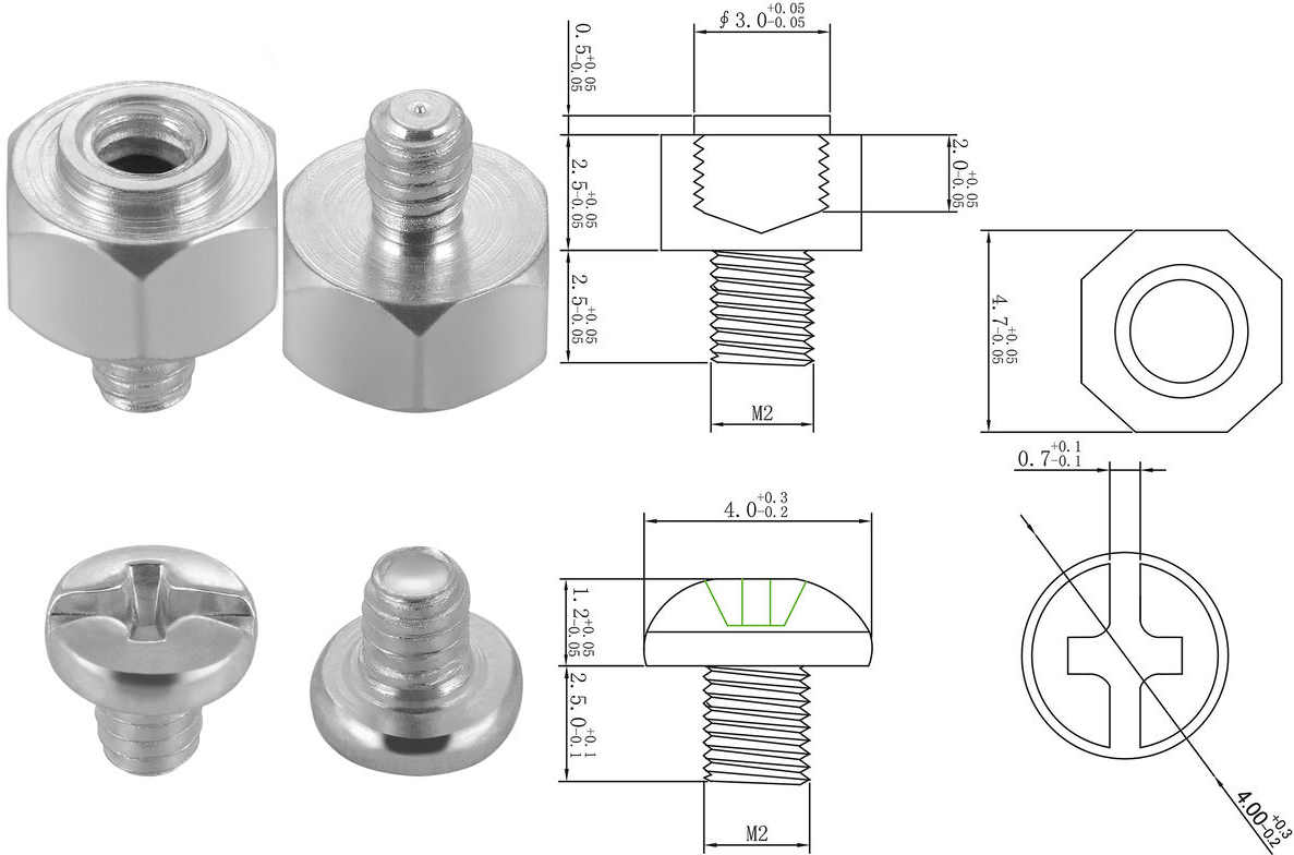
- some propagate a stand-off with inner and outer thread; their outer thread is 2.5mm long. They'd always scratch a plated hole, except you wide the hole and use a nut. - This was the only finding for that type of SMT mounts' drawing w/ measures on it, but some are strange there: e.g. the inner thread is likely not 3.0mm... (i-o-threads-spacer.jpg)
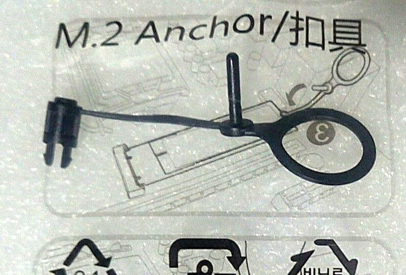
- the clip anchor is obviously not made of conductive material, and covers parts of the RF mounting terminals on the card. (ngff-clip-anchor.jpg)
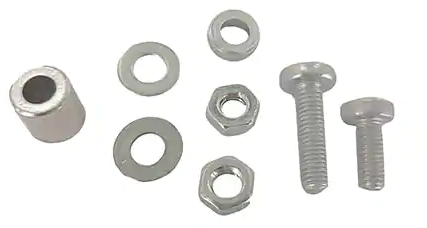
- for the UDOO SBC, a very simple mounting kit gets sold (udoo-mounting-kit-pk.png) which consists of two generic metric screws w different legth, and each two spacer, nuts and washer.
Neither of those are especially elegant for out use case, only the last option is something we could consider.
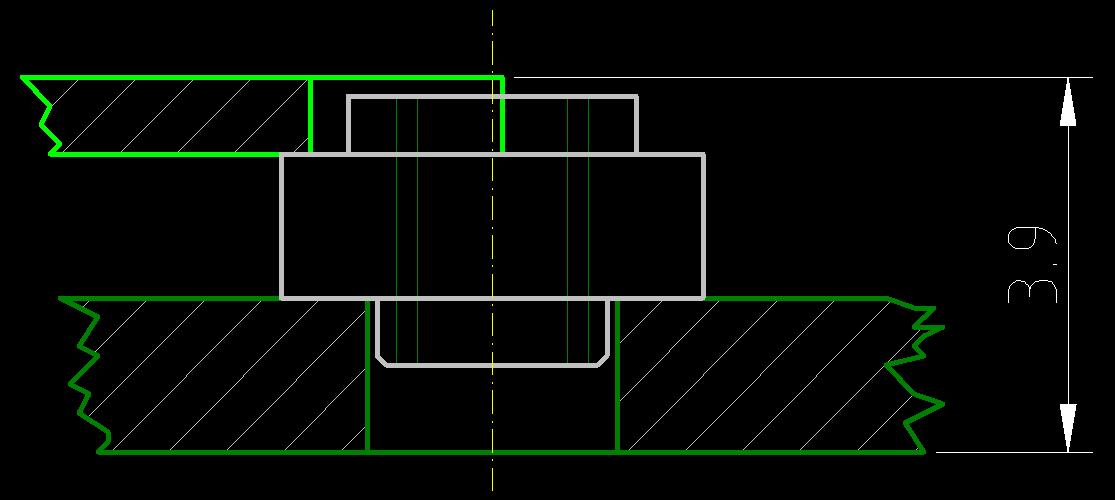
One change we should do anyway as it would allow to mount double-sided cards, is to change to the 2,45mm card offset (insted of now 1,45mm): PC-SIG spec states those two default heights, manufacturer hence offer them. In our case, the 2,45mm-TE-type with B key would be 2199230-3 for the M.2 connector (instead of 2199119-3), and respective stand-off is SM3ZS067U410-NUT1. This is only a two-liner BoM change. - This change would also ease the wafer-head screw procurement situation, as only one M2x2mm is needed per PCBA, the 2nd can be an easier-to-source M2x3; also 2x M2x2,5 is then possible.
If the overall number of needed wafer-head M2 in 2mm is halved with that change to one per PCBA, we again could think of source them from a random eb*y seller...
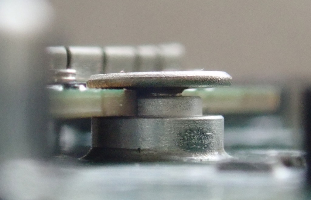
Some retailer use normal DIN 7985 M2 screws in 2mm on top side even w/o a washer (screw head diam is nom. 4mm on M2 DIN7985). While this likely works, they are of course not broad-head of wafer-head screws, the latter with very low-profile head. Higher heads give less mounting freedom for the MHF4 pigtails. - But such screw would be perfectly sane on bottom side, even better with washer.
Updated by laforge over 3 years ago
Problem also seems to exist with SIM8200: https://twitter.com/nixdab/status/1333707836489129984
Updated by mschramm over 3 years ago
The SIM8200-M2 is a 3052 card, so mechanically it will fit the upcoming design.
Updated by mschramm over 3 years ago
dodo34 wrote:
Is there a plan to change the micro-b to Type-C USB ?
The changed design for a v3 candidate is ready in the repo; we only have to decide and select sourcing of a proper (re)movable mounting post solution in favour of extending possible usage also for 3052 cards. Except this, there was no plan to touch the USB3 section.
The view on that might change until a production run, but unlikely.
Updated by mschramm over 3 years ago
mschramm wrote:
[...] the 2,45mm-TE-type with B key would be 2199230-3 for the M.2 connector (instead of 2199119-3), and respective stand-off is SM3ZS067U410-NUT1. This is only a two-liner BoM change.
Parts have arrived and were mechanically tested OK. So we could also incorporate this change in a v3.
Updated by laforge over 3 years ago
mschramm wrote:
mschramm wrote:
[...] the 2,45mm-TE-type with B key would be 2199230-3 for the M.2 connector (instead of 2199119-3), and respective stand-off is SM3ZS067U410-NUT1. This is only a two-liner BoM change.
Parts have arrived and were mechanically tested OK. So we could also incorporate this change in a v3.
please do, and let's try to get the v3 finally out of the door and produced!
Updated by mschramm over 3 years ago
please do, and let's try to get the v3 finally out of the door and produced!
OK!
SYS#5290 has been made for internal processing.
Updated by marwalte about 3 years ago
Hi folks,
I have some feedback regarding accommodation of current 5G data cards.
The 3050 form factor (used by the Telit FN980m) could be accommodated by create a small oblong hole, joined to the 3052 hole already proposed in the v3 board.
An example of this would be the BPlus UN32A - https://www.computextaipei.com.tw/en/product/5DBEC9D7DC3034D6417F918A20ED3D21/info.html
This would need to be plated and connected to ground, per M.2 Spec (3.0 Rev 1.2, Section 2.3.2.1) as laforge mentioned.
Additionally, the 2199230-3 connector should be compatible with the Telit FN980m and similar double-sided boards.
Updated by mschramm about 3 years ago
marwalte wrote:
The 3050 form factor (used by the Telit FN980m) could be accommodated by create a small oblong hole, joined to the 3052 hole already proposed in the v3 board.
Too late for a first v3 production run, PCB panel production already started.
Updated by laforge about 3 years ago
- Status changed from In Progress to Resolved
- % Done changed from 0 to 100
the first batch of v3 of the board design has been manufactured and tested. This issue can be closed.