Bug #4241
closedmeasure insertion loss for two alternatives of RF adapter on VNA up to 3GHz
100%
Description
We want to know insertion loss for both alternatives we are thinking of for placing them on the NGFF breakout PCBA:
- the custom RF cable assembly w/ THT SMA jack (right angle,; don't solder this one, it can be tested self-supporting) and attached pigtail cable, and
- a similar combination w/ a short uFL<->MHF4 cable + THT SMA soldered (on the spare PCB where you already placed the MHF4 on).
For the first part, we don't yet have the MHF4 version but a uFL variant; so additional adapters are needed.
Files
| sma-st-coupler.png | View sma-st-coupler.png | 7.08 KB | sma-sma coupler for reference | ||
| sma-ufl-pigtail.png | View sma-ufl-pigtail.png | 7.04 KB | sma-ufl pigtail | ||
| ngff-sma-180-amc-ufl-sma.png | View ngff-sma-180-amc-ufl-sma.png | 7.35 KB | sma to pcb pcb mhf4 connector amc to ufl to sma | ||
| ngff-sma-180-hsc-ufl-sma.png | View ngff-sma-180-hsc-ufl-sma.png | 7.34 KB | sma to pcb pcb mhf4 connector hsc to ufl to sma | ||
| ngff-sma-180-umc-ufl-sma.png | View ngff-sma-180-umc-ufl-sma.png | 7.54 KB | sma to pcb pcb mhf4 connector umc to ufl to sma | ||
| sma-ufl-pigtail_1.png | View sma-ufl-pigtail_1.png | 7.14 KB | sma-ufl pigtail 1dB scale | ||
| sma-st-coupler_1.png | View sma-st-coupler_1.png | 7.03 KB | sma-sma coupler 1dB scale | ||
| ufl-ufl_cable.png | View ufl-ufl_cable.png | 5.97 KB | vna - sma-ufl adapter - ufl-ufl cable - ufl-sma adapter - vna | ||
| sma-ufl-cable-ufl-sma.png | View sma-ufl-cable-ufl-sma.png | 6.56 KB | vna - sma-mpcie-board - ufl-ufl cable - mpcie-board-sma - vna | ||
| ufl-cable-ufl-sma.png | View ufl-cable-ufl-sma.png | 6.17 KB | vna - sma-mpcie-board - ufl-ufl cable - ufl-sma adapter - vna | ||
| umc2.png | View umc2.png | 7.71 KB | sma to pcb pcb mhf4 connector umc to ufl to sma different cable | ||
| hsc2.png | View hsc2.png | 7.74 KB | sma to pcb pcb mhf4 connector hmc to ufl to sma different cable | ||
| amc2.png | View amc2.png | 7.81 KB | sma to pcb pcb mhf4 connector amc to ufl to sma different cable | ||
| umc3.png | View umc3.png | 7.3 KB | no esd diode on pcb anymore | ||
| hsc3.png | View hsc3.png | 7.32 KB | no esd diode on pcb anymore | ||
| amc3.png | View amc3.png | 7.29 KB | no esd diode on pcb anymore | ||
| amc4.png | View amc4.png | 7.98 KB | no esd diode - different scale | ||
| hsc4.png | View hsc4.png | 7.99 KB | no esd diode - different scale | ||
| umc4.png | View umc4.png | 7.89 KB | no esd diode - different scale | ||
| ngff2_D6.png | View ngff2_D6.png | 8.14 KB | |||
| ngff2_D5.png | View ngff2_D5.png | 8.13 KB | |||
| ngff2_D7.png | View ngff2_D7.png | 8.14 KB |


Updated by roh over 4 years ago
- File sma-st-coupler.png sma-st-coupler.png added
- File sma-ufl-pigtail.png sma-ufl-pigtail.png added
- File ngff-sma-180-amc-ufl-sma.png ngff-sma-180-amc-ufl-sma.png added
- File ngff-sma-180-hsc-ufl-sma.png ngff-sma-180-hsc-ufl-sma.png added
- File ngff-sma-180-umc-ufl-sma.png ngff-sma-180-umc-ufl-sma.png added
- Status changed from New to Resolved
Updated by roh over 4 years ago
- File sma-ufl-pigtail_1.png sma-ufl-pigtail_1.png added
- File sma-st-coupler_1.png sma-st-coupler_1.png added
Updated by roh over 4 years ago
- % Done changed from 0 to 100
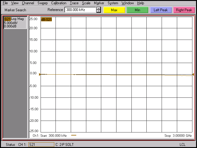
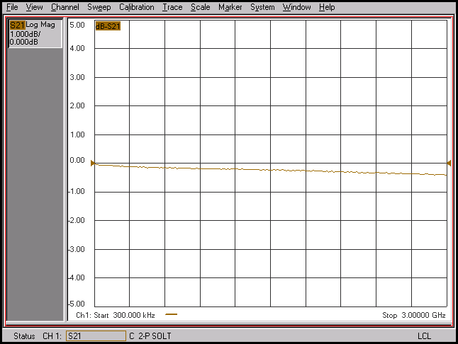
- the ufl pigtail performs best with a performance of 0.2-0.3dB insertion loss over the whole band.
- umc performs the worst with -13dB insertion loss at around 1.6GHz and -10dB at around 3GHz
- amc slopes down to -5dB at around 1GHz and slowly down to -9dB at 3GHz
- hsc also slopes down to -8dB at 3GHz, similar to amc, but with ~1dB better overall performance (less loss)
if we use mhf4 directly on the pcb - the 'hsc' connector seems the best of the batch. recommendation is using the pigtail due to massively better performance.
Updated by laforge over 4 years ago
Hi,
On Wed, Oct 23, 2019 at 03:40:24PM +0000, roh [REDMINE] wrote:
results:
- the ufl pigtail performs best with a performance of 0.2-0.3dB insertion loss over the whole band.
- umc performs the worst with -13dB insertion loss at around 1.6GHz and -10dB at around 3GHz
- amc slopes down to -5dB at around 1GHz and slowly down to -9dB at 3GHz
- hsc also slopes down to -8dB at 3GHz, similar to amc, but with ~1dB better overall performance (less loss)
5, 8, 9 or 13 dB loss are totally unacceptable. There must be something seriously wrong with
either the test setup, or the adapters, cables or our PCB traces are anything but well-matched.
If we cannot improve the situation, the wire-to-SMA pigtail is the only acceptable option :/
Updated by mschramm over 4 years ago
The last two pictures show a gain: parts or all of the graph is in 1st quadrant of the graph (not exclusivly in the fourth) which is clearly not possible.
The three product names of different brands all refer to the same mechanical plug solution, they should not expose these wide differences in measurements.
Updated by roh over 4 years ago
- File ufl-ufl_cable.png ufl-ufl_cable.png added
- File sma-ufl-cable-ufl-sma.png sma-ufl-cable-ufl-sma.png added
- File sma-ufl-cable-ufl-sma.png added
i think this is just a minor calibration error: * i was not redoing calib but loading a saved one * the calib was done on a used sma-sma coupler and sma calib kit, not with ufl or similar connectors
i did some traces on the minipci-e board for comparison (ufl to sma adapter onboard)
Updated by mschramm over 4 years ago
one image is uploaded twice - I think you wanted to upload another screencopy?
Updated by laforge over 4 years ago
- Status changed from Resolved to In Progress
- % Done changed from 100 to 60
- did you double-check / re-confirm the situation with the improbable high loss of the converter involving the PCB trace? Like using another set of MHF4-to-UFL cables / ULF-to-SMA adapter or the like?
- i still have a hard time guessing what the file name of the graphs actually mean in terms of physical cable/adapter/connector comparison. Please explain the results, possibly by creating a small table with human-readable description of the setup next to every graph filename
- did you compare with the mPCIe breakout board trace as requested yesterday?
Updated by roh over 4 years ago
laforge wrote:
- did you double-check / re-confirm the situation with the improbable high loss of the converter involving the PCB trace? Like using another set of MHF4-to-UFL cables / ULF-to-SMA adapter or the like?
not yet - i am currently on that.
- i still have a hard time guessing what the file name of the graphs actually mean in terms of physical cable/adapter/connector comparison. Please explain the results, possibly by creating a small table with human-readable description of the setup next to every graph filename
i put a long description in the optional filedescription. but its only displayed on top of the page
ufl-ufl_cable.png          vna - sma-ufl adapter - ufl-ufl cable - ufl-sma adapter - vna  'only the ufl-ufl cable (sma-ufl adaptes both sides)'
sma-ufl-cable-ufl-sma.png  vna - sma-mpcie-board - ufl-ufl cable - mpcie-board-sma - vna  'loop through mpcie-board (connect ufl cable twice, use board as adapter on both ports'
ufl-cable-ufl-sma.png      vna - sma-mpcie-board - ufl-ufl cable - ufl-sma adapter - vna  'one side sma-ufl adapter - other side mpci-e board'
i would expect the first having the best measurement results, the second the worst and the last should be most realistic and somewhere in the middle - which measurements confirm.
- did you compare with the mPCIe breakout board trace as requested yesterday?
thats what the last 3 graphs are all about.
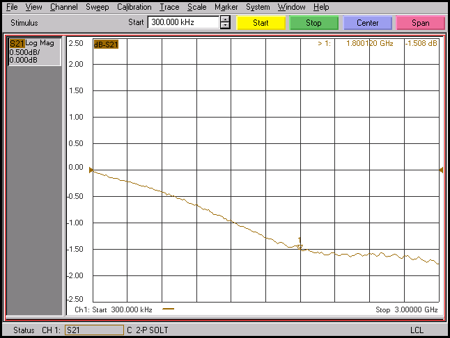
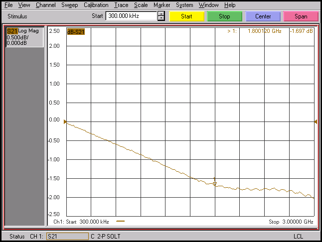
Updated by roh over 4 years ago
- File umc3.png umc3.png added
- File hsc3.png hsc3.png added
- File amc3.png amc3.png added
- File amc4.png amc4.png added
- File hsc4.png hsc4.png added
- File umc4.png umc4.png added
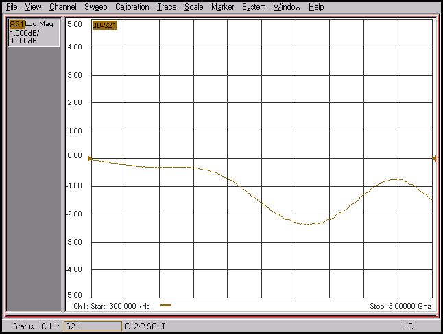
the next test was removing the esd protection diode, and the attenuation went away.
these are the amc3/umc3/hsc3 graphs
still not ideal values, but all were better than -2dB now (see *4 graphs for better y scale)
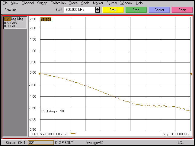
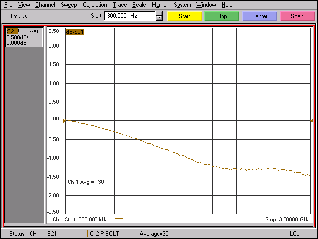
Updated by roh over 4 years ago
- File ngff2_D5.png ngff2_D5.png added
- File ngff2_D6.png ngff2_D6.png added
- File ngff2_D7.png ngff2_D7.png added
- Status changed from In Progress to Resolved
- % Done changed from 60 to 100
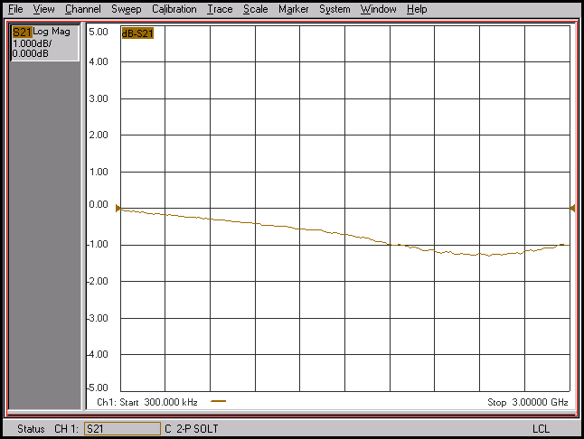
new testrun with new pcb and new diodes:
D5 = ESDAXLC6-1BT2 - digikey# 497-13413-1-ND
D6 = SESD0402X1BN-0010-098 - digikey# SESD0402X1BN-0010-098CT-ND
D7 = SESD0402X1BN-0015-096 - digikey# SESD0402X1BN-0015-096CT-ND
from the graphs i'd say we use the one selected for D5 in this case.
the mhf4 connector used was the 'cheapest one' of the tested ones. (could not see a proper difference inbetween the amc4/umc4/hsc4 graphs)

